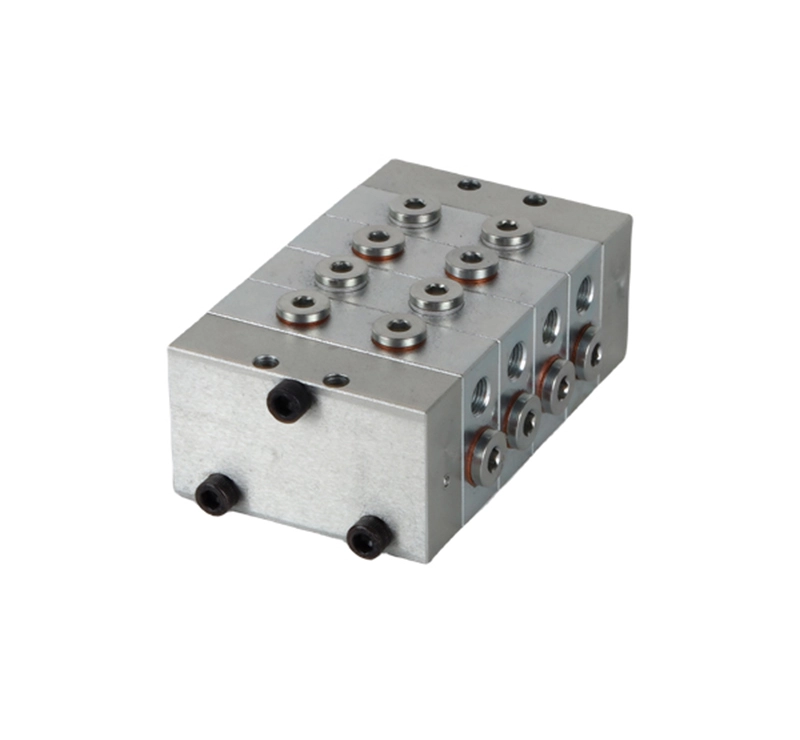
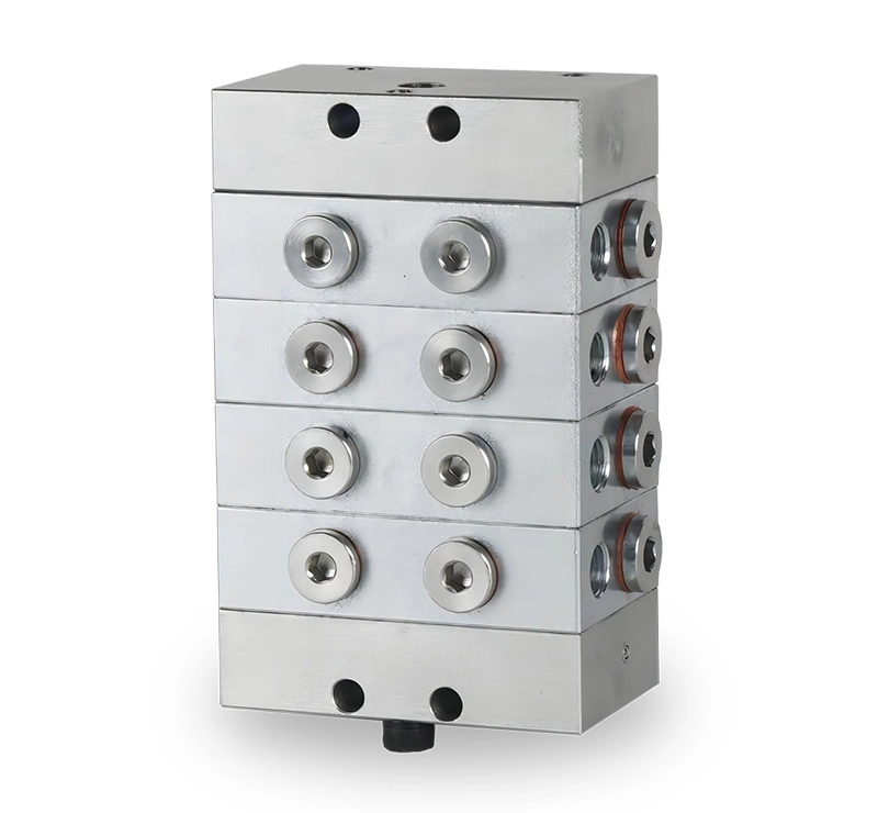
A typical VE distributor valve consists of a “first piece,” a “tail piece,” and 3 to 10 working pieces, providing lubrication to 3 to 20 points. The VE distributor valve offers a variety of displacement specifications to choose from.
The double outlet working piece (indicated by “T”) has two oil outlets, which can be configured for side or upper output. The single outlet working piece (indicated by “S”) has one oil outlet, located at either end, with the other end requiring a block. It’s important to note that blocking any outlet on the double outlet working piece will affect normal operation.
Magnetic and electronic proximity switch cycle indicators can be easily integrated to ensure reliable lubrication and system protection.
Technical Information of VE Distributor Valve
| Technical parameters | |
| Operating pressure | Max 25Mpa |
| Lubricants | Oil 46 cSt to Grease NLGI-2 |
| Operating temperature | -40 °C to 110 °C |
| Inlet port | G1/8 |
| Outlet port | M10x1 |
| Outlets | Max. 20 |
| Max. number of operations | Max. 200cyc/min (When there is no indicator rod)
Max.60cyc/min(When installing the indicator rod) |
| Coating | Zinc-Nickel plated |
| Lubrication system | progressive lubrication system |
Technical Drawing of VE Distributor Valve

| Number of work | A(mm) | B(mm) | Number of work | A(mm) | B(mm) |
| 3 | 107.9 | 90 | 7 | 187.9 | 170 |
| 4 | 127.9 | 110 | 8 | 207.9 | 190 |
| 5 | 147.9 | 130 | 9 | 227.9 | 210 |
| 6 | 167.9 | 150 | 10 | 247.9 | 230 |
Characteristics of VE Distributor Valve
- Universal use in continuous or intermittent operation
- Internal consolidation of outlets
- The built-in check valve can ensure the accuracy of each lubricant filling flow
- Visual or electrical monitoring optional


There are no reviews yet.